Mirror Reflection PhysicsLaw of Reflection & Angle of Incidence
Introduction
Mirror reflection is the geometric rule that governs how a flat surface redirects a ray of light: the angle at which the ray arrives equals the angle at which it departs, both measured from the normal to the surface. That relationship, written θᵢ = θᵣ, is called the law of reflection. It holds for any flat reflective surface regardless of the incoming direction, and it applies whether the surface is tilted, vertical, or horizontal.
Designers of optical instruments rely on this law at every step. A periscope bends a line of sight through two 90° turns using nothing but two flat mirrors. A laser scanner steers a beam across a page by rotating a small mirror by fractions of a degree. Telescope alignment procedures, rear-view mirror geometry, and cinema projection systems all reduce to the same θᵢ = θᵣ relationship applied once or several times in sequence.
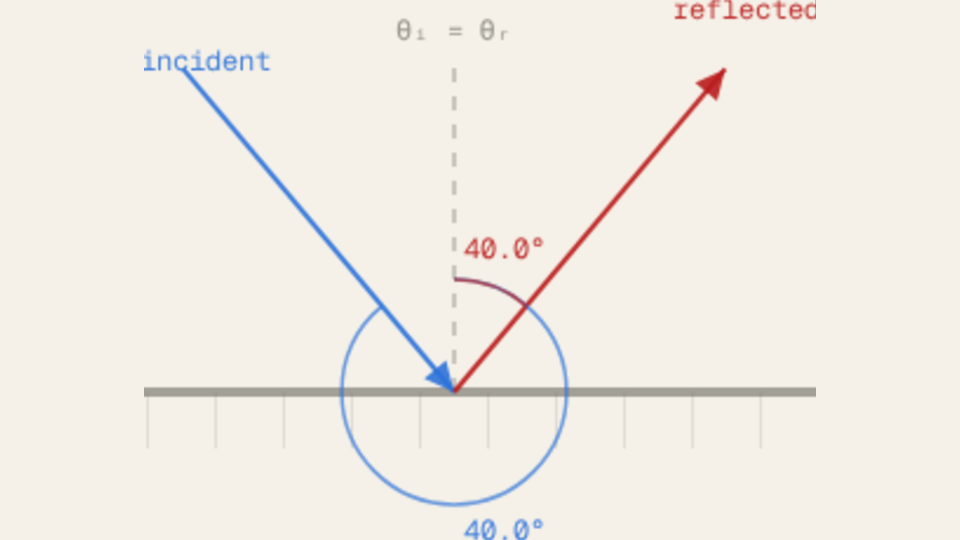
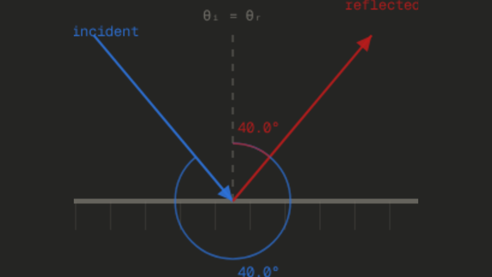
Most people arriving at this topic expect the reflected ray to stay horizontal whenever the surface is horizontal, regardless of where the incoming ray originates. The Reflected angle readout in the simulator contradicts that picture at once: with the Incident angle slider at 40° and the Mirror tilt slider at 0°, the readout shows 40.0°, not 0°. The reflected ray is not horizontal; it is the mirror image of the incident ray about the normal, which points straight up when the tilt is zero.
The Physics Explained
The normal to a flat mirror is the line perpendicular to its surface at the point of contact. For a horizontal mirror the normal points straight up, so its direction vector is (dx, dy) = (0, 1). When the Mirror tilt slider is set to 30°, the mirror rotates 30° from horizontal and the normal rotates with it: the normal direction becomes (sin 30°, cos 30°) = (0.500, 0.866). For a tilt of −45° the formula gives (sin(−45°), cos(−45°)) = (−0.707, +0.707), which points up and to the left, consistent with a mirror tilted 45° clockwise from horizontal. The sign of the x-component tracks the direction of tilt, and the y-component remains positive as long as the tilt stays within ±90°, meaning the normal always points toward the upper half-plane.
The incident ray and the reflected ray are both measured against this normal, not against the mirror surface itself. With the Incident angle slider at 40° and the Mirror tilt slider at 0°, the simulator draws the blue incident ray arriving at 40° from the vertical normal and the red reflected ray departing at 40° on the other side. The Incident angle readout shows 40.0° and the Reflected angle readout shows 40.0°, confirming the equality. Changing the Mirror tilt slider to 20° rotates the entire geometry: the Normal angle readout climbs from 90.0° to 110.0°, the incident and reflected rays both pivot with the normal, and the two readouts still agree at 40.0° each.
A notable special case appears when the Incident angle slider is set to 45° and the Mirror tilt slider is left at 0°. The incident ray arrives at 45° from the upward normal, meaning it travels diagonally downward at 45° to the vertical. The reflected ray departs at 45° on the other side of the normal, which sends it horizontally. This is the periscope configuration: a 45° flat mirror bends a vertical line of sight into a horizontal one. The physics module comment in the source code labels this the "classic periscope case" precisely because the geometry falls out of the law of reflection with no additional assumptions.
The mirror tilt slider ranges from −45° to +45°, and at every combination with the incident angle slider (5° to 85°) the equality θᵢ = θᵣ holds. The angle arcs drawn on the canvas at the contact point are color-coded: blue for θᵢ, red for θᵣ. Both arcs carry the same numeric label, which updates live as either slider moves. The θᵢ = θᵣ label that fades in above the normal once the animation completes is a direct visual assertion of the law, not a consequence of any particular slider position.
Key Equations
Both angles are measured from the normal to the mirror surface at the point of contact, not from the surface itself. With the Incident angle slider at 40° and the Mirror tilt slider at 0°, the Incident angle readout shows 40.0° and the Reflected angle readout shows 40.0°. Sliding the Mirror tilt to 30° changes the orientation of the normal but leaves both readouts at 40.0°, confirming that the equality is independent of mirror orientation.
Here φ is the mirror tilt angle measured from horizontal. At φ = 0° this gives n = (0, 1), a normal pointing straight up. At φ = 45° it gives n = (0.707, 0.707), pointing up and to the right. At φ = −45° it gives n = (−0.707, +0.707), pointing up and to the left. The Normal angle readout in the simulator displays the angle this vector makes with the horizontal: 90° + φ, so 90° when the mirror is flat and 135° when the Mirror tilt slider is at 45°.
When the mirror rotates by Δφ, the normal rotates by Δφ, the angle of incidence measured from the new normal shifts by Δφ, and by the law of reflection the angle of reflection shifts by the same Δφ. Because the reflected ray is on the opposite side of the normal from the incident ray, the absolute change in the reflected ray's direction is twice the mirror rotation. Setting the Mirror tilt slider from 0° to 10° while holding the Incident angle slider at 40° shifts the Normal angle readout from 90.0° to 100.0° and rotates the red reflected ray on the canvas by 20°, matching Δα = 2 × 10° = 20°.
Key Variables
| Symbol | Name | Unit | Meaning |
|---|---|---|---|
| θᵢ | Angle of incidence | ° | Angle between the incoming ray and the normal at the contact point |
| θᵣ | Angle of reflection | ° | Angle between the outgoing ray and the normal; equals θᵢ by the law of reflection |
| φ | Mirror tilt | ° | Rotation of the mirror from horizontal; ranges from −45° to +45° in the simulator |
| n | Normal direction | dimensionless | Unit vector perpendicular to the mirror surface, given by (sin φ, cos φ) |
| Δα | Beam deviation | ° | Change in reflected ray direction when the mirror rotates; equals twice the mirror rotation |
Real World Examples
How do periscopes use flat mirrors to redirect a line of sight?
A periscope contains two flat mirrors, each tilted at 45° to the vertical. When the incident angle equals 45°, the law of reflection places the reflected ray exactly perpendicular to the incoming one, redirecting light through a 90° turn. Two such turns let a submarine crew see above the waterline without exposing any part of the vessel.
The geometry follows directly from θᵢ = θᵣ: at θᵢ = 45° with mirror tilt 0°, the incident ray arrives at 45° from the normal (which points straight up), and the reflected ray departs symmetrically at 45° on the other side, producing a horizontal output ray. Setting the Incident angle slider to 45° and the Mirror tilt slider to 0° in the simulator puts the Reflected angle readout at 45.0°, confirming the 90° total deviation that the periscope exploits.
Each additional flat mirror in an optical relay applies the same rule independently, so a chain of mirrors can redirect a beam through any sequence of angles while the equality θᵢ = θᵣ holds at every surface.
Why does rotating a mirror by one degree steer the reflected beam by two degrees?
When a mirror rotates by an angle φ, its normal rotates by the same φ. Because the incident ray direction is fixed, the angle between the incident ray and the new normal changes by φ, so θᵢ shifts by φ. By the law of reflection θᵣ also shifts by φ, and because the reflected ray is on the opposite side of the normal, the reflected ray's absolute direction changes by 2φ.
This two-to-one lever is the operating principle of galvanometer-based laser scanners and optical tweezers. Setting the Mirror tilt slider to 10° in the simulator while keeping the incident angle fixed at 40° shifts the Normal angle readout from 90.0° to 100.0°; the reflected ray rotates visibly by 20° on the canvas, matching the 2× rule.
Precision scanning systems exploit this by driving a small mirror with a servo motor and achieving twice the angular scan range from the same mechanical motion. A mirror rotating through ±15° sweeps a laser beam through ±30°, covering a 60° field without moving the laser source.
How do bathroom mirror cabinets create the illusion of infinite depth?
Two parallel flat mirrors facing each other trap a ray between them through repeated reflections. At each bounce the law of reflection applies: θᵢ = θᵣ measured from the normal of that surface. Because the mirrors are parallel their normals are antiparallel, so each reflection preserves the ray's angle with respect to the pair and the ray bounces back and forth, growing dimmer at each pass due to the finite reflectivity of real glass.
The result is a receding tunnel of images, each one representing one additional round trip. The brightness of the k-th image scales as Rk, where R is the mirror's reflectivity (typically 0.96 to 0.99 for a quality silver-backed mirror). After 50 round trips a 0.97-reflectivity mirror transmits only 0.97100 ≈ 0.048 of the original intensity, which is why the tunnel appears to fade into darkness rather than continuing indefinitely.
The simulator captures the single-bounce version of the same rule. With the Incident angle slider at 40° and the Mirror tilt slider at 0°, the Incident angle readout and the Reflected angle readout both read 40.0°, confirming that every individual reflection in the infinite-depth chain obeys exactly the same equation.
Further Reading
- Elastic collision: a moving ball rebounding from a hard wall leaves with its angle of incidence equal to its angle of reflection, the mechanical analogue of a light ray bouncing off a mirror.
- Projectile motion: another geometric path problem where angle choices determine the shape of a trajectory, offering a useful contrast with the linear geometry of reflected rays.
- Simple pendulum: a system whose small-angle restoring force shares the same geometric sine and cosine decomposition that appears in the normal-direction formula for a tilted mirror.