Mirror Reflection · SimulatorAngles from the Normal
A flat mirror and a draggable incident ray; reflected ray always matches angle of incidence
Published: June 25, 2026
Objective
Verify the law of reflection on a flat plane mirror: the angle of incidence equals the angle of reflection, where both angles are measured from the normal to the mirror surface, not from the surface itself. The simulation models a point-source ray and an ideal, perfectly flat mirror with no absorption, scattering, or phase shift.
Setup
- Leave both sliders at their defaults: incident angle 40°, mirror tilt 0°. Observe the mirror bar and the dashed normal line at canvas center before pressing Start.
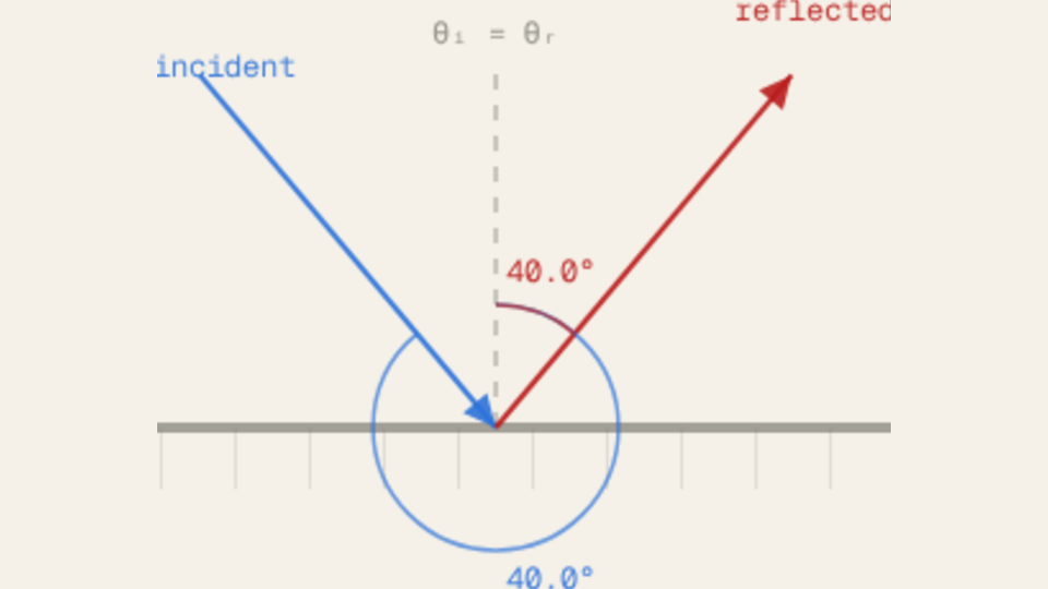
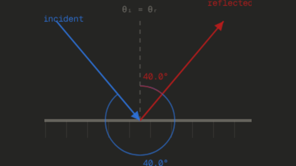
- Press Start and watch the incident ray (blue) animate toward the contact point, then the reflected ray (red) appear. Note that both angle labels at the contact point show 40.0°.
- Press Reset. Drag the incident angle slider to 20°, press Start again, and record the two angle readouts in the HUD.
- Press Reset. Drag the incident angle slider to 70°, press Start, and record the readouts again. Compare the three pairs: 20°/20°, 40°/40°, 70°/70°.
- Press Reset. Set incident angle back to 40° and drag the mirror tilt slider to 30°. Press Start. Note that the reflected ray now points in a visibly different direction but the HUD still shows θᵢ = θᵣ = 40.0°.
Analytical Prediction
The law of reflection states θᵣ = θᵢ for any angle of incidence, regardless of mirror orientation. With the default settings (incidentAngle = 40°, mirrorTilt = 0°):
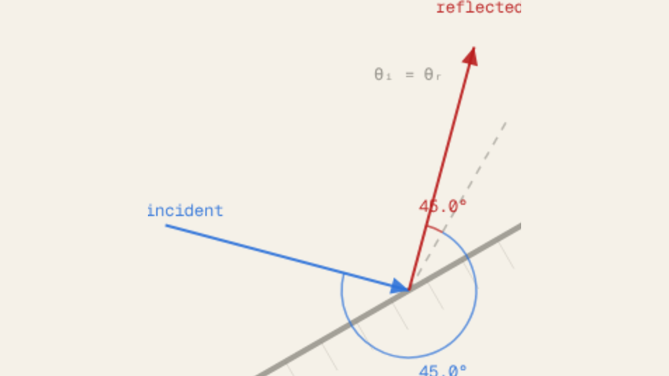
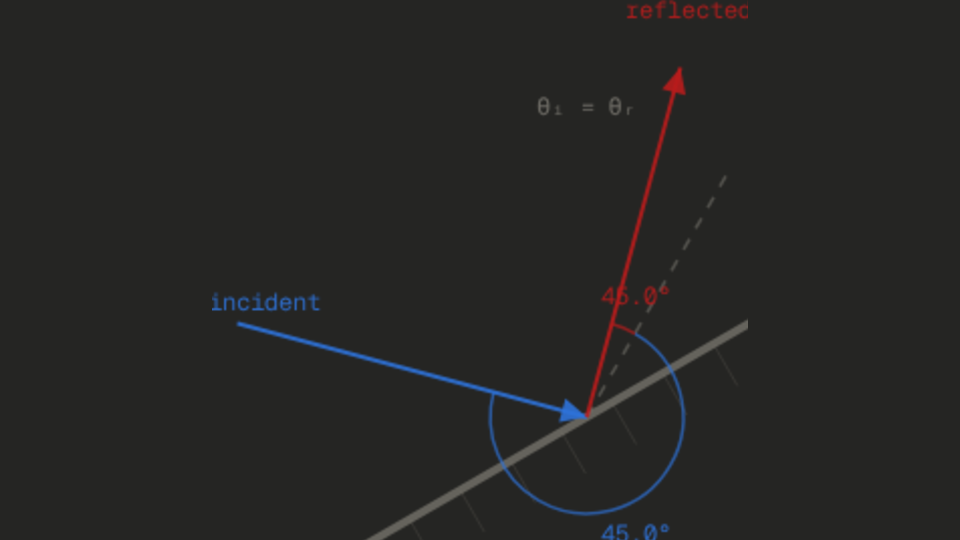
At incidentAngle = 45° and mirrorTilt = 0°, the reflected ray is exactly horizontal (90° from the normal axis in the vertical direction), because both rays make a 45° angle with the vertical normal:
When mirrorTilt = 30°, the normal rotates to 120° from horizontal. The HUD reads normalAngle = 90 + 30 = 120.0°, and the reflected ray direction rotates accordingly, but the equality θᵢ = θᵣ is unchanged.
Results Analysis
After each run, read the thetaI and thetaR readouts in the HUD. They should match to within 0.1°. At the default 40° setting, both display 40.0°. The mirrorTiltOut readout shows the mirror tilt set by the slider, and normalAngleOut shows 90 + mirrorTilt (the angle of the normal measured from horizontal, in degrees). Changing mirrorTilt from 0° to 30° changes normalAngleOut from 90.0° to 120.0°, confirming the normal rotates with the mirror. The ghost overlay accumulates past angle pairs so you can visually confirm that at every tested angle, the incident and reflected rays are symmetric about the dashed normal line.
Source of Error
This simulation assumes a perfectly flat, ideal mirror with 100% reflectance and no surface roughness. Real mirrors have a thin glass layer causing partial back-surface reflection, wavelength-dependent reflectance, and micro-scale roughness that produces diffuse scattering. The point-source ray is a geometric abstraction; real beams have finite width and diffract at the mirror edge. The model also ignores polarization effects at non-normal incidence (Fresnel equations) and the phase shift on reflection from a denser medium. Because both the sim and the analytical prediction share these idealizations, the residual difference between HUD readouts and the prediction is purely numerical, not physical.
Further Exploration
- Set the incident angle to 45° and mirrorTilt to 0°. The reflected ray should be exactly horizontal. Can you find another angle where the reflected ray is perpendicular to the incident ray? (Hint: try 45°.)
- Drag mirrorTilt from −45° to +45° while the incident angle is fixed at 40°. How many degrees does the reflected ray rotate for every degree of mirror tilt? Is the relationship linear?
- Set incidentAngle to 5° (nearly grazing). The incident and reflected rays are almost parallel to the mirror surface. Does the HUD still show θᵢ = θᵣ? Why is this the hardest case to verify visually without the normal reference line?
- After several runs at different angles, observe the ghost overlay. Can you pick a combination where three different incident angles all result in reflected rays that pass through the same point on the canvas?
- In a real periscope, two mirrors each tilted at 45° redirect a light ray by 90° twice, returning it parallel to the original direction. Set mirrorTilt to 45° and incidentAngle to 45° and trace where the reflected ray points. Is the total deflection consistent with the periscope principle?