Polarizing Filter (Malus's Law) Physicscos²θ Law & Light Extinction
Introduction
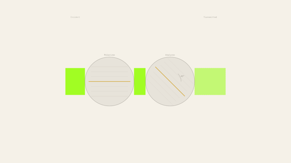
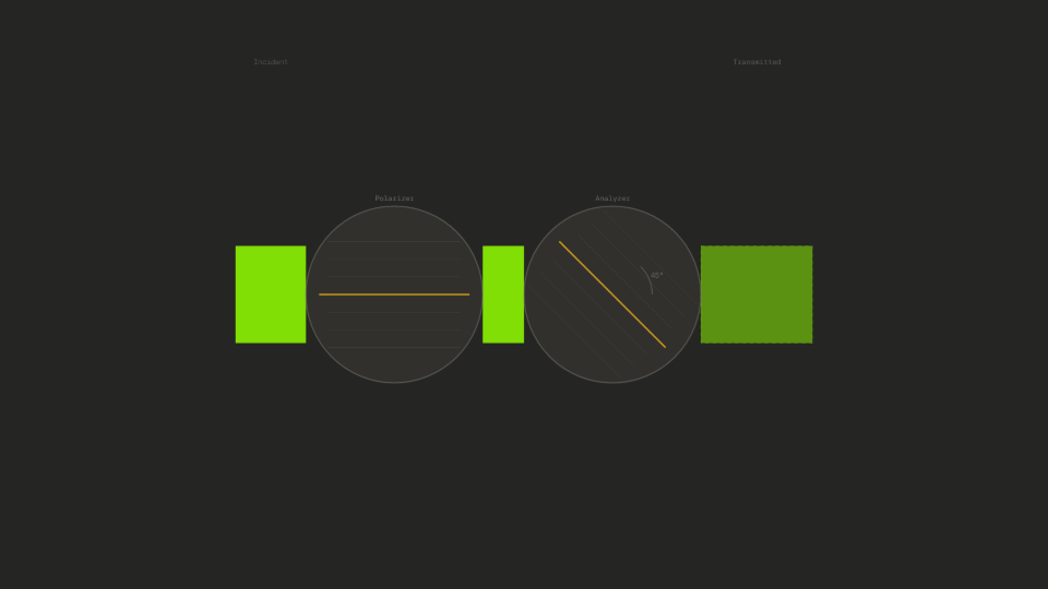
When light passes through a polarizing filter, its electric field oscillations are restricted to a single plane. A second filter (the analyzer) placed downstream with its transmission axis rotated by angle θ relative to the first then passes only the component of the electric field aligned with its own axis. The resulting transmitted intensity follows Malus's Law: I = I₀·cos²θ, where I₀ is the intensity entering the analyzer and θ is the angle between the two filter axes.
The law matters across a wide range of technology. LCD screens use crossed polarizers and a voltage-controlled liquid-crystal layer to switch individual pixels between bright and dark states. Polarizing sunglasses exploit the same geometry to suppress glare from horizontal surfaces. Optical communications systems use polarization-sensitive components to route signals without electrical conversion. Each application is a direct engineering use of the cos²θ dependence.
Before running the simulator, most people assume intensity falls roughly in proportion to the angle: rotate to 45° and expect roughly half the reduction, rotate to 90° and expect a complete block, with a smooth linear drop in between. The ratio I/I₀ readout tells a different story: at θ = 45° the ratio reads 0.500 (exactly half the original intensity survives), but the approach to zero is much faster near 90° than a linear ramp would predict, because the cosine itself decreases steeply in that range before the cos² drives it to a true null.
The Physics Explained


Light is a transverse electromagnetic wave: the electric field oscillates perpendicular to the direction of travel. An ideal linear polarizer transmits only the component of the electric field aligned with its transmission axis, blocking the perpendicular component entirely. Unpolarized light emerging from a source contains a random mixture of all orientations; the polarizer passes half the total intensity on average and produces a beam whose electric field oscillates along a single fixed direction. In the simulator, this polarized beam is the incident input that the analyzer acts on.
The analyzer's job is to project that incoming electric field onto its own transmission axis. If the incoming field amplitude is E₀ and the analyzer is rotated by θ, the projected amplitude is E₀·cos θ. Intensity is proportional to the square of the amplitude, so the transmitted intensity is I₀·cos²θ. This is Malus's Law, derived from a single vector projection. With θ = 45° and I₀ = 60 W/m² (the simulator's defaults), the formula gives I = 60·cos²(45°) = 60·0.5 = 30.0 W/m², which the I (W/m²) readout confirms.
The cos²θ curve is concave, not linear. At small angles the intensity barely changes: cos²(10°) = 0.970, meaning only 3% of the incident intensity is lost at 10° of rotation. The curve then steepens through the mid-range and accelerates toward zero near 90°. With I₀ = 60 W/m² and θ set to 70°, the readout shows I = 60·cos²(70°) ≈ 60·0.117 = 7.0 W/m², a loss of nearly 88% from a rotation that is only 78% of the way to 90°. This curvature is what surprises most first-time users.
Wavelength does not enter the formula. Malus's Law holds for all visible wavelengths, because it follows from the geometry of electric-field projection rather than from any resonance or dispersive property of the material. The wavelength slider (400–700 nm) changes the beam's rendered color on the canvas but leaves the I (W/m²) and ratio I/I₀ readouts unchanged at any fixed θ and I₀, confirming that the law is a purely geometric result independent of the light's color.
Key Equations
This is the central result. I₀ is the intensity of the linearly polarized light entering the analyzer and θ is the angle between the polarizer's transmission axis and the analyzer's transmission axis. With the simulator's defaults (I₀ = 60 W/m², θ = 45°): I = 60 · cos²(45°) = 60 · 0.500 = 30.0 W/m². The I (W/m²) readout shows 30.0, and the ratio readout shows 0.500, both consistent with the formula. Setting θ to 0° returns I = 60 · 1 = 60.0 W/m² (full transmission); setting θ to 90° returns I = 60 · 0 = 0.0 W/m² (complete extinction).
The ratio form shows that Malus's Law is purely a function of angle, the initial intensity I₀ cancels. At θ = 30°, the ratio = cos²(30°) = (√3/2)² = 0.750, so 75% of the intensity survives regardless of whether I₀ is 10 W/m² or 100 W/m². The ratio I/I₀ readout tracks this directly: with I₀ = 100 W/m² and θ = 30°, the readout shows 0.750 and I reads 75.0 W/m²; with I₀ = 10 W/m² and the same angle, the ratio readout still shows 0.750 while I reads 7.5 W/m².
Malus's Law follows from this one-step projection. The incoming beam has electric field amplitude E₀. The analyzer passes the component along its axis, which is E₀·cos θ. Intensity scales as the square of the field amplitude (I ∝ E²), so I = I₀·cos²θ. This derivation clarifies why the law applies to all wavelengths: the projection is geometric and depends only on the angle, not on the frequency of the wave. Setting θ = 45° gives Et = E₀·cos(45°) = E₀·(√2/2) ≈ 0.707·E₀, and squaring yields the ½ factor that puts the intensity at exactly 30.0 W/m² for I₀ = 60 W/m².
Key Variables
| Symbol | Name | Unit | Meaning |
|---|---|---|---|
| θ | Analyzer angle | ° | Angle between the polarizer transmission axis and the analyzer transmission axis (0–90°) |
| I₀ | Initial intensity | W/m² | Intensity of the linearly polarized beam entering the analyzer |
| I | Transmitted intensity | W/m² | Intensity of the beam exiting the analyzer; equals I₀·cos²θ |
| I/I₀ | Intensity ratio | dimensionless | Fraction of incident intensity transmitted; equals cos²θ, independent of I₀ |
| λ | Wavelength | nm | Wavelength of the light; affects color rendering but not the intensity ratio |
| E₀ | Electric field amplitude | V/m | Amplitude of the incoming electric field; I₀ ∝ E₀² |
Real World Examples
Why do polarizing sunglasses cut road glare so effectively?
Light reflected from a flat horizontal surface (road asphalt, water, wet pavement) becomes partially polarized with its electric field oscillating predominantly in the horizontal direction. A polarizing sunglass lens has its transmission axis oriented vertically, so the reflected glare arrives at roughly θ = 90° relative to the lens axis. Malus's Law predicts I = I₀·cos²(90°) = 0, which means the reflected glare is almost completely blocked.
Overhead sunlight, by contrast, is unpolarized and passes through the lens at roughly half intensity on average (the integral of cos²θ over all orientations equals ½), so the sky appears uniformly dimmer without losing scene detail. The ratio I/I₀ readout in the simulator reaches 0.000 when θ is set to 90°, matching the extinction the lens provides for horizontally polarized glare.
Polarizing sunglasses use geometry rather than tinted absorption: the vertical transmission axis is the engineering choice that targets the dominant polarization direction of reflected glare. The I₀ slider demonstrates the ratio principle, changing I₀ from 60 W/m² to 100 W/m² at θ = 90° leaves the ratio at 0.000 and I at 0.0 W/m², because the cos²(90°) factor is zero regardless of incident intensity.
How does an LCD screen use crossed polarizers to switch pixels on and off?
A liquid-crystal display sandwiches a thin layer of liquid-crystal molecules between two polarizing sheets whose transmission axes are crossed at 90°. With no voltage applied, the liquid-crystal layer rotates the polarization of incoming light by 90°, so the light that exits the first polarizer arrives at the second one aligned with its axis (θ = 0°) and passes through at full intensity: the pixel appears bright. When a voltage is applied, the liquid-crystal molecules align with the field and stop rotating the polarization. Light leaving the first polarizer now hits the second at θ = 90°, and Malus's Law delivers I = I₀·cos²(90°) = 0: the pixel goes dark.
The on/off contrast ratio of a modern LCD panel is the ratio between these two extreme states, a number that display engineers pursue relentlessly. The extinction condition is visible in the I (W/m²) readout, which falls to 0.0 W/m² at θ = 90° regardless of the I₀ slider setting, confirming that the cos² relationship drives the display to a true null rather than a merely dim state.
Intermediate gray levels are produced by intermediate voltages that rotate the liquid-crystal molecules only partway, placing the effective θ somewhere between 0° and 90°. At θ = 60° with I₀ = 60 W/m², the readout shows I = 60·cos²(60°) = 60·0.25 = 15.0 W/m², or 25% of peak brightness, corresponding to a quarter-brightness gray level on the display panel.
Why does a polarizing filter improve outdoor photography at 45° to the sun?
Scattered skylight is most strongly polarized at 90° to the direction of the sun. When a photographer points the camera 90° away from the sun, the sky's scattered light arrives at the lens highly polarized in one plane. Rotating the filter's transmission axis to cross that polarization plane reduces the sky's apparent brightness dramatically, deepening blue tones and making clouds stand out against a darker background.
The degree of sky darkening is governed by Malus's Law: the photographer rotates the filter until the sky component arrives near θ = 90° relative to the filter axis, driving I toward zero for the polarized fraction. Reflected light from foliage and water is also partially polarized, and the same rotation suppresses those reflections simultaneously.
With I₀ = 60 W/m² and θ swept from 0° to 90° in the simulator, the I readout traces the full cos² curve from 60.0 W/m² down to 0.0 W/m², matching the range of control a photographer experiences when rotating the filter on the lens. The steeper drop between 60° and 90° (where I falls from 15.0 W/m² to 0.0 W/m² across just 30° of rotation) is why a small final twist of the filter produces a disproportionate darkening effect in the viewfinder.
Further Reading
- Double-slit experiment: wave interference in the same electromagnetic framework, showing how light's wave nature produces the intensity fringes that underpin modern optical metrology.
- Snell's Law ray optics: the refraction geometry that governs how polarized light bends at a dielectric interface, including Brewster's angle where reflected light becomes completely polarized.
- Wave speed on a string: the mechanical-wave analogue of transverse oscillations, building the field-and-amplitude intuition that carries over directly to electromagnetic polarization.