Snell's Law PhysicsRefraction Angle & Index of Refraction
Introduction
Snell's Law states that when a ray crosses the boundary between two transparent media, the product n·sinθ is conserved: n₁·sinθ₁ = n₂·sinθ₂. Here n₁ and n₂ are the refractive indices of the first and second medium, and θ₁ and θ₂ are the angles the incident and refracted rays make with the normal to the interface. The law follows from the requirement that the component of the wave's phase velocity along the boundary must be the same on both sides, so the wavefronts stay continuous as they cross.
The index ratio controls three linked outcomes: how much the ray bends, whether a partial reflection occurs alongside refraction, and whether refraction is possible at all. When light passes from a denser medium into a less dense one (n₁ greater than n₂), the refracted ray bends away from the normal. Push the incident angle past the critical angle θc = arcsin(n₂/n₁) and the refracted ray cannot form; all energy reflects back. This total internal reflection underpins optical fibres, prismatic reflectors, and diamond brilliance. The Fresnel s-polarisation reflectance Rs = ((n₁·cosθ₁ − n₂·cosθ₂)/(n₁·cosθ₁ + n₂·cosθ₂))² quantifies the partial reflection that accompanies every non-TIR crossing.
Most people expect a steeper incident angle to always produce a steeper refracted angle, with the two tracking each other in a roughly linear way. The θ₂ readout in the simulator contradicts this: with n₁ = 1.00 and n₂ = 1.50 the refracted angle is always smaller than the incident one, and the relationship is distinctly non-linear near grazing incidence. Swap the indices to n₁ = 1.50 and n₂ = 1.00, increase θ₁ past about 41.8°, and the θ₂ readout switches from a numeric value to the TIR label, while the refracted ray vanishes entirely from the canvas.
The Physics Explained
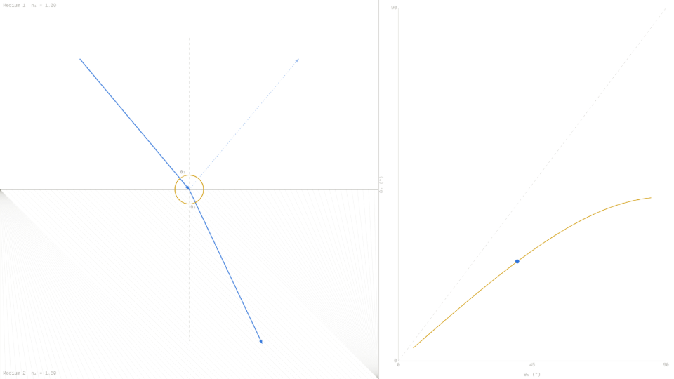
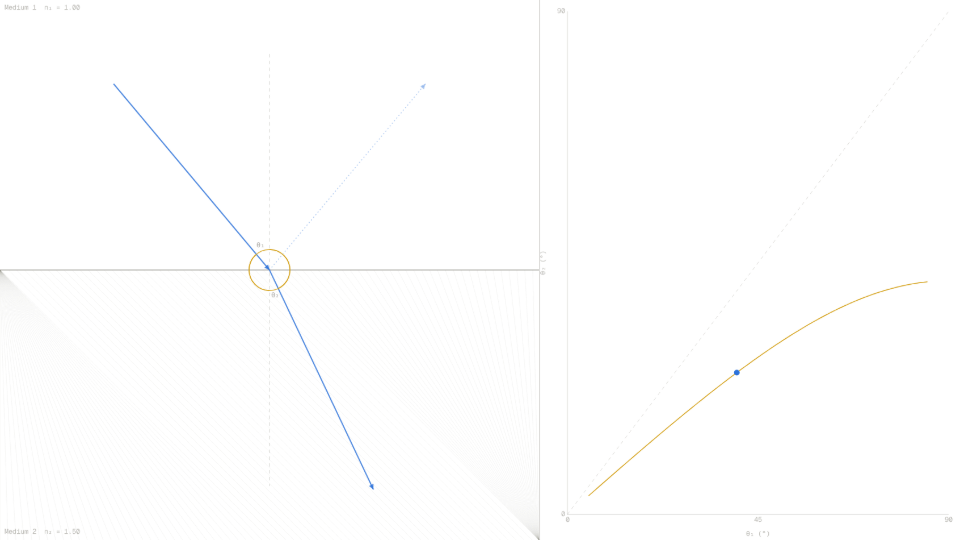
The simulator's default state sets n₁ = 1.00 (air), n₂ = 1.50 (glass), and θ₁ = 40°. Applying Snell's Law: θ₂ = arcsin(1.00 · sin 40° / 1.50) = arcsin(0.6428 / 1.50) = arcsin(0.4285) ≈ 25.4°. The θ₂ readout reports 25.4 and the n₁·sinθ₁ readout reports 0.6428, confirming that the conserved quantity is matched on both sides of the interface. The refracted ray on the canvas bends toward the normal, as expected when passing into a denser medium.
The Fresnel s-polarisation reflectance for the same configuration is Rs = ((1.00·cos40° − 1.50·cos25.4°) / (1.00·cos40° + 1.50·cos25.4°))² = ((0.7660 − 1.3539) / (0.7660 + 1.3539))² = (−0.5879 / 2.1199)² ≈ 0.077. The Reflectance readout in the simulator shows 0.077, meaning about 7.7% of the ray's amplitude is reflected at normal incidence conditions and the rest transmits. The partial reflected ray appears on the canvas as a fainter dashed line on the same side of the interface as the incident ray.
Raising n₁ above n₂ and then sweeping θ₁ upward reveals the critical-angle regime. With n₁ = 1.50 and n₂ = 1.00, the critical angle is θc = arcsin(1.00/1.50) ≈ 41.8°. At θ₁ = 40° the θ₂ readout shows 74.6° and the refracted ray sits nearly parallel to the interface. At θ₁ = 42° the θ₂ readout switches to TIR, the refracted ray disappears from the left canvas panel, and a "Total Internal Reflection" badge renders in red. The right-panel graph shows the θ₂(θ₁) curve terminating at a vertical dashed line at θc, with no curve plotted beyond it.
Equal indices eliminate the boundary entirely. Setting n₁ = n₂ = 1.00 at any θ₁ produces θ₂ = θ₁ with no bend and Rs = 0. The Reflectance readout confirms zero and the refracted ray continues straight through. This limit is why anti-reflection coatings aim to match effective indices at an interface: a perfect index match would produce no reflected power at all.
Key Equations
With the default slider values of n₁ = 1.00, n₂ = 1.50, θ₁ = 40°: the left side evaluates to 1.00 · sin(40°) = 0.6428. Dividing by n₂ = 1.50 gives sin(θ₂) = 0.4285, so θ₂ = arcsin(0.4285) ≈ 25.4°. The n₁·sinθ₁ readout in the simulator holds at 0.6428 throughout the run, showing the conserved quantity directly.
For n₁ = 1.50, n₂ = 1.00: θc = arcsin(1.00/1.50) = arcsin(0.6667) ≈ 41.8°. The simulator draws a faint dashed guide line on the canvas at this angle and marks it θc. At θ₁ = 41° the θ₂ readout still returns a value near 79°; at θ₁ = 42° it switches to TIR, confirming the threshold sits between those two integer-degree steps.
At n₁ = 1.00, n₂ = 1.50, θ₁ = 40°, θ₂ ≈ 25.4°: numerator = 1.00·0.7660 − 1.50·0.9026 = 0.7660 − 1.3539 = −0.5879; denominator = 0.7660 + 1.3539 = 2.1199; Rs = (−0.5879/2.1199)² ≈ 0.077. The Reflectance readout confirms 0.077. As θ₁ approaches θc in the TIR configuration, the numerator approaches the denominator and Rs approaches 1.000, which the readout reaches exactly once TIR activates.
This is the form the simulator evaluates directly. When the argument of arcsin exceeds 1 (that is, when n₁·sinθ₁ > n₂), no real solution exists and the function returns null; the code treats this as TIR. For n₁ = 1.00, n₂ = 1.50, θ₁ = 40°: argument = 0.6428/1.50 = 0.4285, well below 1, so a refracted ray exists at 25.4°. Raising θ₁ to 85° with the same indices gives argument = 0.9962/1.50 = 0.664, still below 1, so TIR never occurs when going from air into glass regardless of the incident angle.
Key Variables
| Symbol | Name | Unit | Meaning |
|---|---|---|---|
| n₁ | Index of first medium | dimensionless | Ratio of the speed of light in vacuum to its speed in medium 1 |
| n₂ | Index of second medium | dimensionless | Ratio of the speed of light in vacuum to its speed in medium 2 |
| θ₁ | Incident angle | ° | Angle between the incident ray and the normal to the interface |
| θ₂ | Refracted angle | ° | Angle between the refracted ray and the normal; null under TIR |
| θc | Critical angle | ° | Incident angle above which TIR occurs; defined only when n₁ > n₂ |
| Rs | Fresnel reflectance (s-pol) | dimensionless | Fraction of ray power reflected at the interface for s-polarised light |
Real World Examples
Why does a straw appear bent when placed in a glass of water?
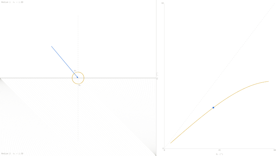
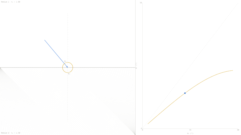
The straw appears bent because light traveling from water (n ≈ 1.33) into air (n = 1.00) bends away from the normal at the surface. Your eye traces the emerging rays straight back, placing the submerged portion at a shallower apparent depth than its true position. The refraction angle is entirely governed by the index ratio: setting n₁ = 1.33 and n₂ = 1.00 in the simulator, with θ₁ = 40°, puts the θ₂ readout at roughly 58.7°, a 18.7° outward bend that the visual system interprets as a positional shift.
The effect grows as the straw is tilted further from vertical, because larger incident angles produce larger fractional bends for the same index ratio. Past θ₁ ≈ 48.8° (the critical angle for water-to-air), no light escapes upward at all, which is why a swimming pool seen at a glancing angle shows a mirror-like patch rather than a view of the bottom.
How do optical fibres guide light around bends without losing the signal?
An optical fibre works by total internal reflection. The core glass has a higher refractive index (typically n₁ ≈ 1.48) than the surrounding cladding (n₂ ≈ 1.46). Any ray that strikes the core-cladding boundary at an angle greater than the critical angle θc = arcsin(1.46/1.48) ≈ 80.6° bounces back into the core with no transmitted ray on the cladding side. The simulator shows the TIR badge appearing and the θ₂ readout switching to TIR when n₁ is set above n₂ and θ₁ exceeds θc.
Because the reflected ray obeys the same geometry at the next wall, the light zigzags down the fibre indefinitely. Engineers squeeze the index contrast to control which ray angles are guided and which leak out, tailoring the fibre's acceptance cone for specific bandwidths and bend-radius tolerances. The right-panel curve in the simulator, with n₁ = 1.48 and n₂ = 1.46, shows how narrow the angular window between normal transmission and TIR becomes when the two indices are nearly equal.
Why do diamond gemstones sparkle more than glass ones?
Diamond has a refractive index of about 2.42, far above glass at 1.5. The critical angle for diamond-to-air is θc = arcsin(1/2.42) ≈ 24.4°, compared with ≈ 41.8° for glass. Setting n₁ = 2.42 and n₂ = 1.00 in the simulator confirms that TIR activates as soon as θ₁ exceeds roughly 24°. Because most rays bouncing around inside a cut diamond meet a facet at well above 24°, they reflect rather than transmit, and the gem traps and redirects light through its top facets.
The gem cutter's job is to orient those facets so that most trapped rays eventually exit upward toward the viewer at high brightness. Glass, with its shallower critical angle, leaks far more light out the sides and bottom, producing a duller appearance. The Reflectance readout near θc with n₁ = 2.42 climbs steeply toward 1.000, mirroring the near-perfect internal mirror that makes each facet act as a silvered surface without any metallic coating.
Further Reading
- Wave speed on a string: how the wave-speed equation governs the analogous phase-matching condition that underlies Snell's Law at a mechanical boundary.
- Coulomb's Law: another inverse-square field law where the ratio of medium properties (permittivity) controls the field strength, paralleling the role of refractive index in optics.
- Projectile motion: angle-dependent trajectory physics that shares the same trigonometric framework used to decompose ray directions at an interface.