Polarizing Filter (Malus's Law) · SimulatorTransmitted Intensity via cos²θ
Polarized light through a filter at adjustable angle; transmitted intensity follows cos²θ
Published: June 28, 2026
Objective
Verify Malus's Law, which states that the intensity transmitted through a polarizer-analyzer pair follows I = I₀·cos²θ, where θ is the angle between the two polarization axes. The simulation idealizes both polarizers as perfect linear polarizers with no absorption losses except the cos²θ factor, and treats the incident beam as fully polarized.
Setup
- Set the Analyzer Angle θ slider to 0° (both polarizers aligned). Note the Transmitted I readout and confirm it equals the Initial Intensity I₀ you set (default 60 W/m²). Record this as your baseline.
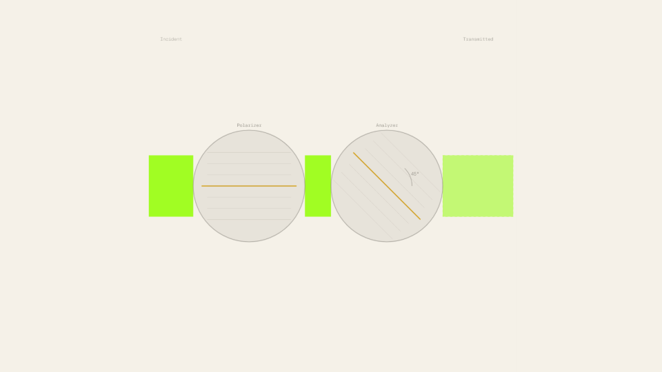
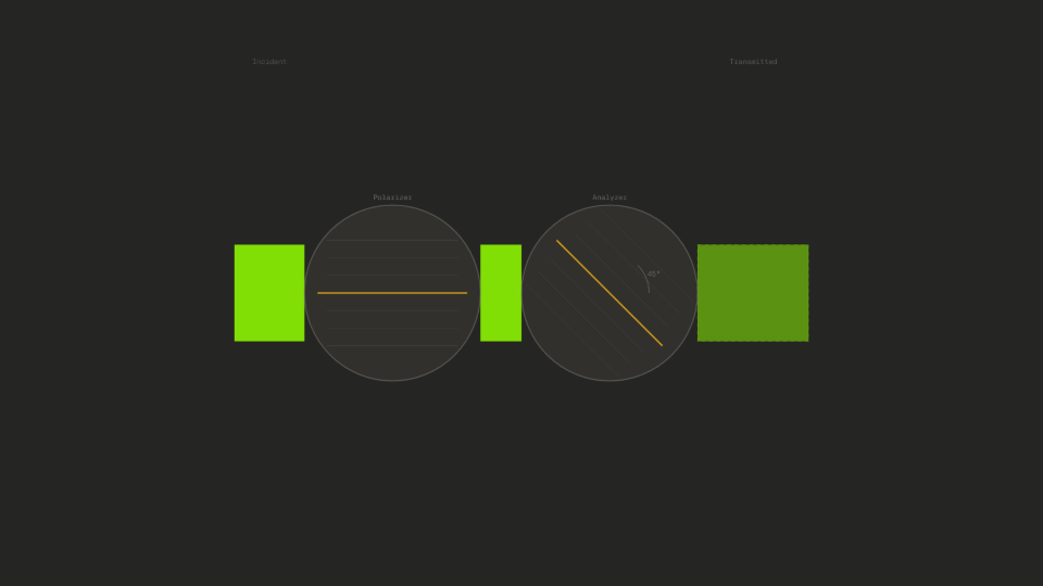
- Move θ to 45° and record the Transmitted I readout. Predict before looking: is it 75%, 50%, or 25% of I₀?
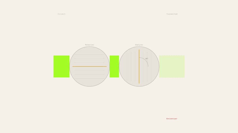
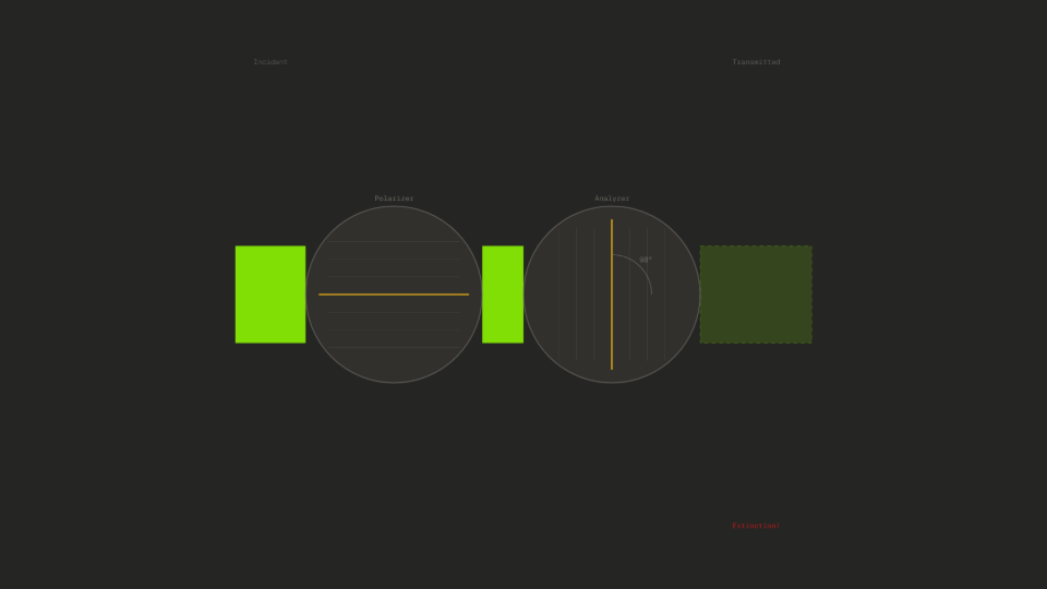
- Move θ to 90° and observe the transmitted beam on the physical view. Record the Transmitted I and Ratio I/I₀ readouts.
- Press Start with θ = 45° and I₀ = 60 W/m². Watch the analyzer disk animate to 45°. Confirm the Ratio I/I₀ readout settles to 0.500.
- Sweep the Wavelength λ slider from 400 nm to 700 nm while watching the Ratio I/I₀ readout. Note whether the ratio changes.
- Reset, set I₀ to 100 W/m² and θ to 60°, press Start, and read the Transmitted I. Predict: I = 100 · cos²(60°) = 100 · 0.25 = 25.0 W/m².
Analytical Prediction
Malus's Law gives the transmitted intensity as I = I₀·cos²θ. With I₀ = 60 W/m² and θ = 45°:
The Ratio I/I₀ = cos²(45°) = 0.500, confirming exactly half the intensity is transmitted at the 45° midpoint. For the 60° case with I₀ = 100 W/m²:
At θ = 90°, cos²(90°) = 0, so I = 0 regardless of I₀. The ratio law holds: the fractional shape cos²θ is completely independent of I₀ and wavelength λ.
Results Analysis
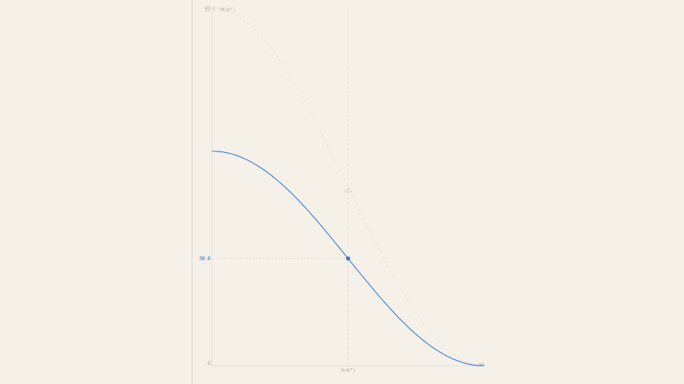
After Start with θ = 45° and I₀ = 60 W/m², the Ratio I/I₀ readout should settle to 0.500 and the Transmitted I readout to 30.0 W/m² (within 0.1 W/m²). At θ = 0°, Transmitted I should equal I₀ exactly and Ratio should read 1.000. At θ = 90°, Transmitted I should read 0.0 W/m² and the transmitted beam on the physical view should be invisible. Sweeping the Wavelength λ slider through 400–700 nm should leave Ratio I/I₀ unchanged at the current θ, confirming wavelength-independence. The Malus curve in the graph panel shows the full cos²-shape from 0° to 90°, with the live operating point (sky blue dot) tracing the curve as θ changes.
Source of Error
This simulation models both polarizers as ideal linear polarizers with 100% transmission at θ = 0° and zero reflection or scattering losses. Real polaroid sheets absorb some fraction even at perfect alignment (typically 3–8% loss), and they transmit a small residual at θ = 90° rather than true zero. The beam is modeled as perfectly monochromatic and fully polarized; partially polarized or unpolarized input would give a different formula. No optical path length, diffraction, or interference effects are included. Because the transmitted intensity is computed analytically from the closed-form cos²θ at every frame rather than numerically integrated, there is no accumulation or truncation error. The residual between the predicted 30.0 W/m² and the readout is therefore purely numerical rounding in the display, not a physical discrepancy.
Further Exploration
- Set θ to 60° and I₀ to 60 W/m². The formula predicts I = 60 · cos²(60°) = 15 W/m². Does the readout confirm this? How does 15 W/m² compare to the 30 W/m² at 45°, even though the angle only increased by 15°?
- Sweep θ slowly from 0° to 90° while watching the Malus curve graph. At which angle does the operating point move fastest down the curve? Where does it move slowest? Can you relate this to the slope of cos²θ?
- Set I₀ to 10 W/m² and then 100 W/m² at the same θ = 45°. Does the Ratio I/I₀ readout change? What does this tell you about whether cos²θ is an absolute or relative law?
- Sweep λ from 400 nm (violet) to 700 nm (red) while watching the Ratio I/I₀ readout at θ = 45°. The beam color changes but the ratio stays at 0.500. Why does Malus's Law hold equally for all visible wavelengths?
- Set θ = 90° (crossed polarizers). The transmitted beam disappears. Now imagine inserting a third polarizer at 45° between the two crossed ones. What fraction of the original intensity would survive? (Hint: apply Malus's Law twice.)