Free-Body Diagram Builder PhysicsResolve Forces & Find Net Acceleration
Introduction
A free-body diagram is a picture of a single object with every force acting on it drawn as an arrow from a common point. It is the first tool any physics student reaches for, because it turns a vague question, "what does this block do?", into a precise vector sum that Newton's second law can solve. This simulator places a block on an inclined surface, lets you set its mass, the incline angle, the kinetic friction coefficient, and an applied force, then renders all the force arrows live with their magnitudes labeled in newtons.
The setup matters because the same four forces (weight, normal force, friction, and an applied push) recur in nearly every introductory mechanics problem. A crate on a loading ramp, a book held against a wall, a car parked on a hill, and a skier on a slope are all one diagram wearing different numbers. Once you can read the arrows and trust the net-force sum, you can predict acceleration without re-deriving anything, and the simulator's six HUD readouts let you check each component against the formulas one at a time.
It feels self-evident that a heavier block must accelerate faster down the same incline, since gravity pulls it harder. With the incline at 20°, μk at 0.20, and Mass set to 5 kg, the simulator's Acceleration readout settles at 1.51 m/s²; raising Mass to 10 kg doubles the Weight and Net Force readouts but leaves that same 1.51 m/s² on screen. Block mass enters both the gravitational pull and the friction force by the same factor, so it drops out of the acceleration entirely.
The Physics Explained
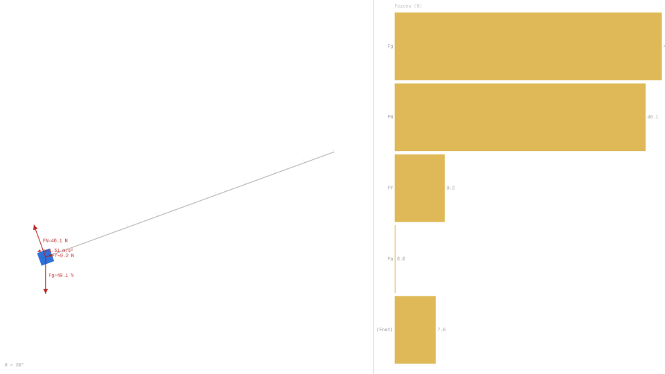
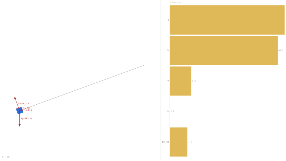
The block on the incline feels up to four forces. Gravity, the weight, acts straight down with magnitude Fg = m·g. The surface pushes back perpendicular to itself with the normal force FN. Kinetic friction runs parallel to the contact face, fighting the slide, with magnitude Ff = μk·FN. An optional applied force Fa pushes along the surface up the slope. To combine them, gravity is split into a component along the slope, Fg·sin θ pointing downhill, and one perpendicular to it, Fg·cos θ pressing into the surface, which the normal force balances.
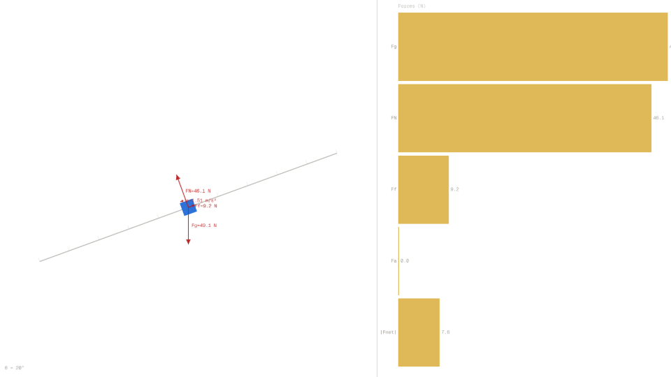
With the simulation defaults Mass = 5 kg, Incline angle = 20°, μk = 0.20, and Applied force = 0 N, the arithmetic is direct. The weight is Fg = 5 × 9.81 = 49.05 N. Pressing into the surface, the normal force is FN = 49.05 × cos 20° ≈ 46.09 N, and friction resists with Ff = 0.20 × 46.09 ≈ 9.22 N up the slope. The downhill pull is Fg∥ = 49.05 × sin 20° ≈ 16.78 N. These are exactly the Weight, Normal Force, and Friction values the simulator's HUD displays the moment the diagram is built.
For a block sliding downhill, the net force along the surface is the downhill pull minus everything resisting it: Fnet = Fg∥ − Ff − Fa = 16.78 − 9.22 − 0 ≈ 7.56 N. Friction always opposes the direction of motion, so this form holds only while the block moves down the slope; if the applied force drives it up the slope, kinetic friction flips to point downhill and the signed readouts show that reversal. Newton's second law then gives the acceleration directly, a = Fnet / m = 7.56 / 5 ≈ 1.51 m/s², which is what the Acceleration readout shows. Both readouts are signed along the surface, positive downhill and negative uphill, so a block driven up the slope shows a negative Net Force. Because the applied force is zero here, the entire balance is gravity fighting friction, and the dotted acceleration arrow points down the slope to mark the direction of motion.
Whether the block accelerates downhill, holds still, or even creeps up depends on how the applied force compares with the imbalance. Adding an applied force of 8 N up the slope with the same angle and friction cuts the downhill pull to about 8.78 N, inside the 9.22 N friction can supply, so the block is held static and both the Net Force and Acceleration readouts fall to 0. Push with 26 N or more and the applied force finally overcomes gravity plus friction, and the block accelerates up the slope instead.
Key Equations
With Mass m = 5 kg, Incline angle θ = 20°, and μk = 0.20 (no applied force), Newton's second law along the surface gives the full chain from weight to acceleration:
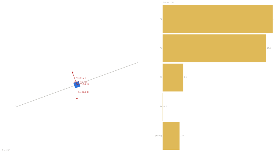
For the default run with m = 5 kg and g = 9.81 m/s²: Fg = 5 × 9.81 = 49.05 N. This is the longest red arrow in the diagram, pointing straight down, and it is the Fg bar, the longest, on the right-hand horizontal bar chart.
For the same defaults at θ = 20°: FN = 49.05 × cos 20° ≈ 46.09 N. On a flat surface (θ = 0°) cos 0° = 1, so FN equals Fg exactly and the FN/Fg ratio reads 1.00.
With μk = 0.20: Ff = 0.20 × 46.09 ≈ 9.22 N, drawn up the slope to oppose downhill sliding. Its magnitude scales with the normal force, so a steeper incline that presses in less firmly also produces less friction.
For the defaults: Fnet = 16.78 − 9.22 − 0 ≈ 7.56 N down the slope. Adding an applied force of 8 N leaves an 8.78 N downhill pull that friction (up to 9.22 N) fully absorbs, so the block is held static with Net Force 0.
For the defaults: a = 7.56 / 5 ≈ 1.51 m/s². Because both Fnet and m double when mass doubles, the Acceleration readout stays at 1.51 m/s² no matter where the Mass slider sits.
Key Variables
| Symbol | Name | Unit | Meaning |
|---|---|---|---|
| m | Block mass | kg | Cancels out of the along-slope acceleration |
| θ | Incline angle | degrees (°) | Tilt of the surface above the horizontal |
| μk | Kinetic friction coefficient | dimensionless | Ratio of kinetic friction to normal force |
| g | Gravitational acceleration | m/s² | 9.81 m/s² downward at Earth's surface |
| Fg | Weight | N | Gravitational pull, drawn straight down |
| FN | Normal force | N | Surface reaction perpendicular to the slope |
| Ff | Kinetic friction force | N | Force opposing the block's downhill motion |
| Fa | Applied force | N | Optional push directed up the slope |
| Fnet | Net force along slope | N | Downhill pull minus friction and applied force |
| a | Acceleration | m/s² | Net force divided by mass |
Real World Examples
Why do engineers draw a free-body diagram before solving any statics problem?
A free-body diagram isolates one object and draws every force acting on it as an arrow, so that Newton's second law can be applied component by component without confusion. Structural engineers sketch one for every beam joint, bridge deck, and crane boom before a single number is computed, because the diagram converts a tangled real-world load case into a clean vector sum.
The simulator makes this discipline concrete. With Mass = 5 kg, Incline angle = 20°, Friction coeff. μk = 0.20, and Applied force = 0 N, the diagram draws weight straight down at 49.05 N, the normal force perpendicular to the surface at 46.09 N, and friction up the slope at 9.22 N. The horizontal bar chart on the right ranks the magnitudes so the dominant force is obvious at a glance, and the Net Force readout of 7.56 N is exactly the along-slope sum that determines motion. An engineer who skips the diagram routinely drops a force or mis-signs a component; the diagram is the audit trail that catches it.
How much force does a worker need to hold a crate steady on a loading ramp?
On a ramp, gravity pulls a crate down the slope with the component Fg·sin θ while friction resists motion with up to μk·FN. To hold the crate steady, a worker only has to push up the slope hard enough that the remaining downhill imbalance drops within what friction can hold.
The simulator demonstrates this directly. Holding Mass = 5 kg, Incline angle = 20°, and Friction coeff. μk = 0.20, the unaided Net Force readout sits at 7.56 N down the slope. Dragging the Applied force slider up to 8 N leaves only about 8.78 N of downhill pull, less than the 9.22 N friction can supply, so static friction makes up the difference and the Net Force and Acceleration readouts both fall to 0. The crate stays held for any push from about 7.6 N up to just under 26 N. One simplification to keep in mind: the simulator uses a single coefficient μk both as the static holding limit and as the kinetic magnitude, whereas real surfaces have a separate static coefficient μs, usually larger than μk, so a real crate holds over a somewhat wider range than these numbers suggest. This is why a single warehouse worker can steady a 5 kg parcel on a gentle ramp with one hand, but the same parcel on a steep 60° chute, where Fg·sin θ jumps far above what friction holds back, would require far more force to control.
Why does a heavier block slide down the same ramp with the same acceleration as a light one?
Mass appears in both the gravitational pull along the slope, Fg·sin θ = m·g·sin θ, and in the friction term, μk·FN = μk·m·g·cos θ. When the net force is divided by mass to get acceleration, the m cancels from every term, leaving a = g·(sin θ − μk·cos θ).
The simulator confirms this cancellation cleanly. Holding Incline angle = 20° and Friction coeff. μk = 0.20, the default 5 kg block reports an Acceleration readout of 1.51 m/s². Dragging the Mass slider from 5 kg up to 10 kg doubles the Weight readout from 49.05 N to 98.10 N and doubles the Net Force readout from 7.56 N to about 15.12 N, yet the Acceleration readout holds steady at 1.51 m/s². This is the same insight Galileo demonstrated by dropping objects of different mass: gravitational acceleration is mass-independent, and adding kinetic friction does not change that, because friction scales with the normal force, which itself scales with mass.
Further Reading
- Inclined plane: the same block-on-a-slope decomposition followed through to slide time and exit speed once the block is released and moving.
- Projectile motion: the same vector-decomposition trick applied to a launched object that splits velocity into independent horizontal and vertical components.