Connected Carts on a Rope · SimulatorPull a Connected System
Two carts connected by a rope, with one pulled by an external force; tension is identical throughout
Published: June 2, 2026
Objective
Verify that the rope between two carts carries only the force needed to accelerate the cart it drags, T = m₂ · a, which is a fixed fraction m₂ ⁄ (m₁ + m₂) of the applied force: the rope never transmits the full pull, and making the dragged cart heavier raises the tension even though the acceleration falls.
Setup
- Set applied force to 20 N, cart 1 mass to 2 kg, and cart 2 mass to 3 kg. Press Start and observe the acceleration and tension values.
- Note the acceleration (a ≈ 4 m/s²) and tension (T ≈ 12 N). Verify that tension is less than the applied force: the rope does not transmit the full external push.
- Reset and increase cart 2's mass to 10 kg while holding force and cart 1's mass constant. Start again and compare the new acceleration and tension to the previous values.
- Observe that increasing m₂ reduces acceleration but increases tension. The tension climbs because the rope must now accelerate a heavier mass, even though the acceleration itself is lower.
- Reset and increase the applied force to 50 N with the default masses. Start and note that acceleration rises to a ≈ 10 m/s² and tension to T ≈ 30 N: both scale in proportion with F, and the tension stays at the same fraction of the pull (3 ⁄ 5 of 50 N), so the rope still never carries the full 50 N.
Analytical Prediction
With F = 20 N, m₁ = 2 kg, m₂ = 3 kg, the system acceleration and rope tension are governed by:
The readouts display a ≈ 4.00 m/s² and T ≈ 12.0 N. Note that T < F: the rope's role is to accelerate cart 2 at the system's rate, not to transmit the applied force unchanged. When m₂ is increased to 10 kg (with F and m₁ held constant), a = 20/12 ≈ 1.67 m/s² and T = 10 × 1.67 ≈ 16.7 N; tension rises despite acceleration falling, because cart 2's mass dominates the T calculation. Raising F to 50 N at the default masses gives a = 50 ⁄ 5 = 10.0 m/s² and T = 3 × 10.0 = 30.0 N: tension scales with F at fixed masses, always as the same fraction 3 ⁄ 5.
Results Analysis
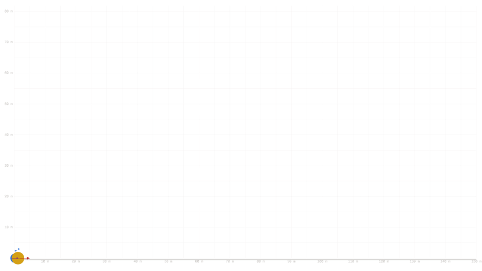
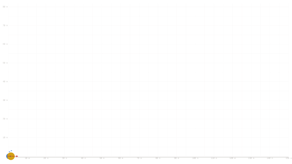
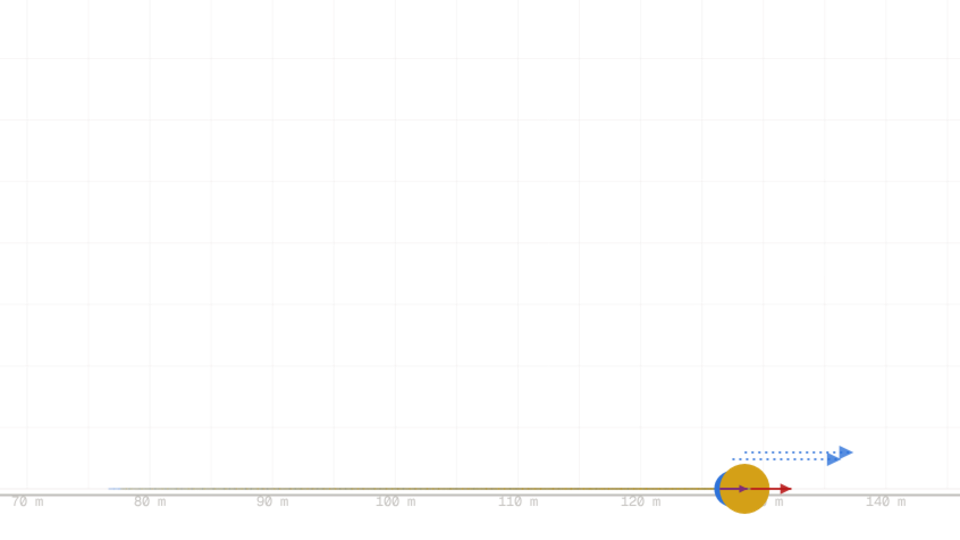
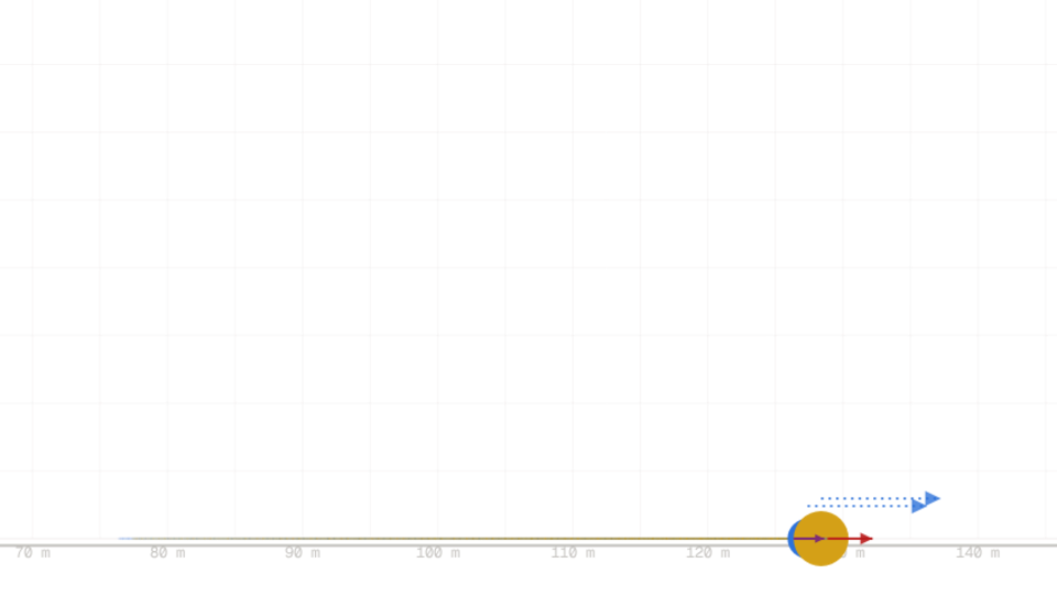
During the simulation, the Acceleration readout shows the system's shared acceleration (computed as a = F/(m₁+m₂)). The Tension readout displays T = m₂ · a. Compare these against hand calculations for the slider settings: both should match to within 0.01 m/s² and 0.1 N respectively, confirming that the rope's job is to impart the force needed to accelerate its own mass at the system's rate. Visually, cart 1 (sky, in front) is pulled by the crimson applied-force arrow and the taut rope drags cart 2 (gold, behind); the plum tension arrow on cart 2 is drawn to the same scale as the applied-force arrow, so their length ratio shows T ⁄ F directly (3 ⁄ 5 at the defaults). Both carts move together with identical velocity vectors.
Source of Error
The simulation assumes ideal rigid carts (point masses) and a massless, inextensible rope. Air resistance and friction are neglected; all acceleration comes from the applied force alone. The numerical integration uses fixed substeps, so position and velocity accumulate small rounding errors over the 8-second run. The readouts round to 2 decimal places, hiding sub-centimetre position drift and tension ripple below 0.1 N. These idealizations are mirrored in the prediction (which assumes the same neglect), so the residual gap is purely numerical, not physical.
Further Exploration
- What happens if you double the applied force while keeping the cart masses constant? Does the tension double, or does it increase by a different factor?
- If you increase cart 1's mass to 10 kg while leaving force and cart 2's mass at their defaults, how does the tension change? Does cart 1's mass affect the rope at all?
- Set cart 2's mass to 1 kg and cart 1's mass to 10 kg, with force at 20 N. Calculate the expected tension by hand, then run the simulation to verify. Does your prediction match the readout?
- Set both cart masses to 10 kg with the force at 50 N. The acceleration drops to 2.5 m/s² and the tension reads 25 N, exactly half the applied force. Why is the fraction one half here, and what mass split would push the tension above half of F?