Double Slit Experiment · SimulatorFringe Spacing and Interference
Light through two slits onto a screen; bright and dark fringes spaced by λL/d, all sliders adjustable.
Published: June 26, 2026
Objective
Explore the double-slit interference pattern and verify that fringe spacing follows Δy = λL/d. Adjust wavelength, slit separation, screen distance, and slit width to observe how each parameter shifts the bright and dark bands. The key idealization is monochromatic, coherent light and slits much narrower than their separation.
Setup
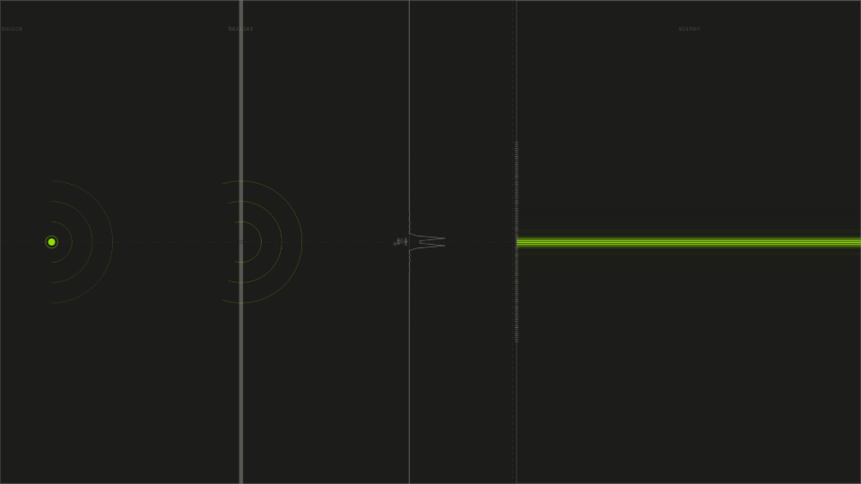
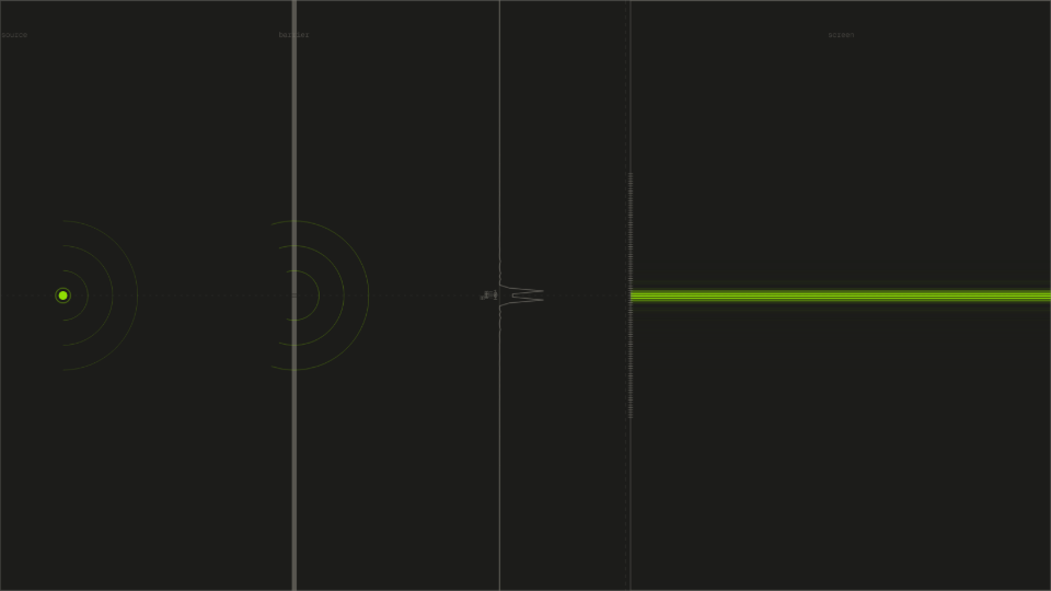
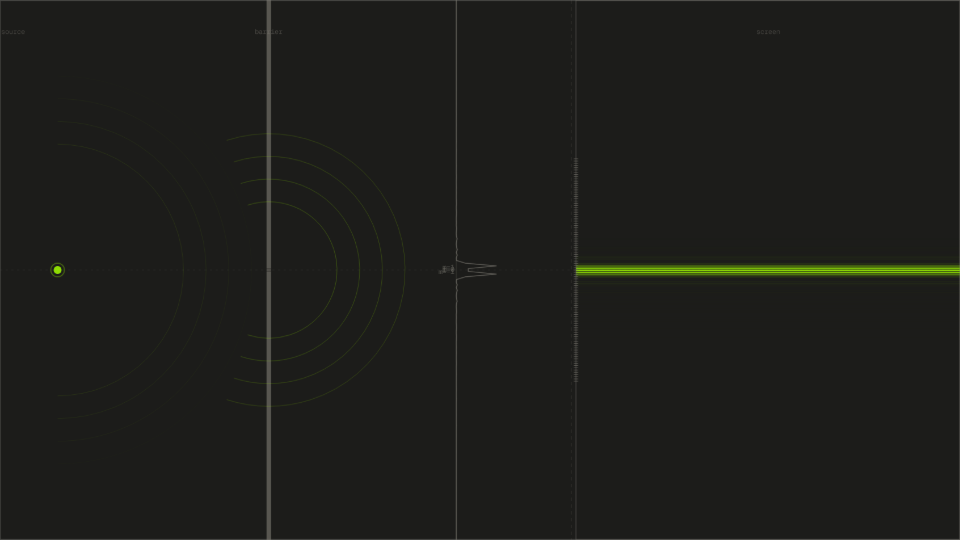
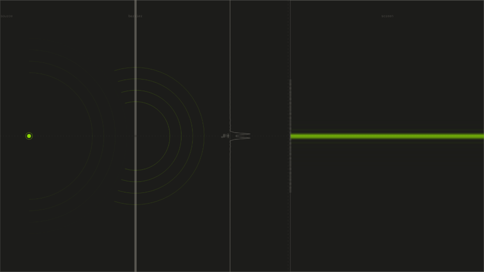
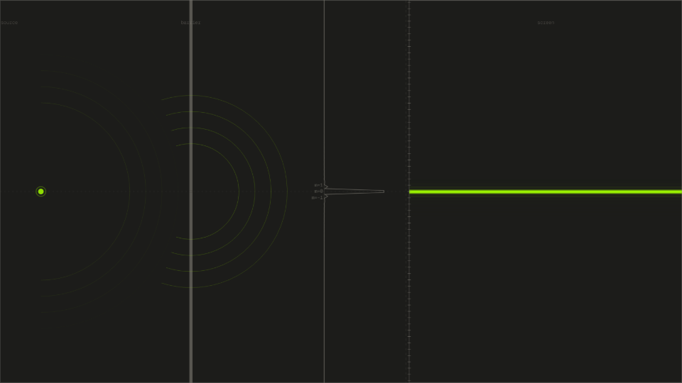
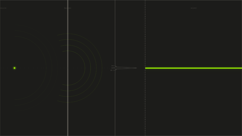
- Leave all sliders at their defaults: wavelength 550 nm, slit separation 0.40 mm, screen distance 1.5 m, slit width 0.10 mm. Press Start and observe the fringe pattern on the screen at right.
- Read the Fringe Spacing readout. It should show approximately 2.063 mm. Record this as your measured spacing for the default configuration.
- Halve the slit separation to 0.20 mm (drag the slider left). Watch the fringe spacing readout and the screen pattern update. Record the new spacing.
- Return slit separation to 0.40 mm and instead double the screen distance to 3.0 m. Record the fringe spacing again.
- Restore screen distance to 1.5 m. Sweep the wavelength slider from 380 nm (violet) to 750 nm (red) and observe both the color change on the screen and the change in fringe spacing.
Analytical Prediction
The fringe spacing formula is Δy = λL/d. Starting from the default values (λ = 550 nm, L = 1.5 m, d = 0.40 mm):
Halving d to 0.20 mm should double the spacing:
Doubling L to 3.0 m (d back to 0.40 mm) should also double the spacing:
For wavelength at 750 nm with defaults otherwise:
Results Analysis
After pressing Start, confirm that the Fringe Spacing readout shows 2.063 mm at the default settings. When slit separation is halved to 0.20 mm, the readout should show approximately 4.125 mm, confirming the inverse relationship: Δy ∝ 1/d. When screen distance is doubled to 3.0 m (slit sep returned to 0.40 mm), the readout should again show approximately 4.125 mm, confirming the proportional relationship: Δy ∝ L. The Screen Distance readout updates live as the slider is dragged. The Wavelength readout tracks the nm value. The Order at 1st Bright readout displays approximately 1.00 for any slider combination, confirming that the first bright fringe always corresponds to path difference equal to one wavelength.
Source of Error
This simulation assumes perfectly coherent, monochromatic light with infinite coherence length, which no real light source produces. The slits are modeled as ideal rectangular apertures with no diffraction at their edges beyond the standard sinc envelope. The screen is treated as infinitely far in the transverse direction, so edge reflections and boundary effects are absent. The model also omits polarization effects and any medium other than vacuum. These idealizations are shared by the analytical prediction above, so they do not contribute to any residual gap between the readout values and the calculated Δy. The gap between the predicted and displayed fringe spacing is therefore purely numerical, not physical.
Further Exploration
- Set wavelength to 380 nm (violet) and then to 750 nm (red). How large is the ratio of the two fringe spacings, and does this match the ratio of the wavelengths?
- Increase slit width from 0.10 mm all the way to 0.40 mm (equal to the slit separation). What happens to the higher-order fringes, and why does the pattern change even though slit separation is unchanged?
- Set screen distance to 3.0 m and slit separation to 0.10 mm. How many visible bright fringes fit on the screen? Compare this to 0.40 mm slit separation at the same screen distance.
- Run the default configuration, then press Reset to archive the profile as a ghost. Change the wavelength to 650 nm and start again. Can you see the fringe spacing difference between the two overlaid profiles?
- Is there a combination of sliders where the first-order fringe falls outside the visible screen area? What does that tell you about the practical limits of the setup in a real laboratory?